

Just another variation on tattoo machine PSU. This one uses off the shelf switching converter module, digital potentiometer, V/I sensor module, OLED display and an arduino. It also has a custom 3D-printed case.
In sections below you can find pictures, description and a source code:
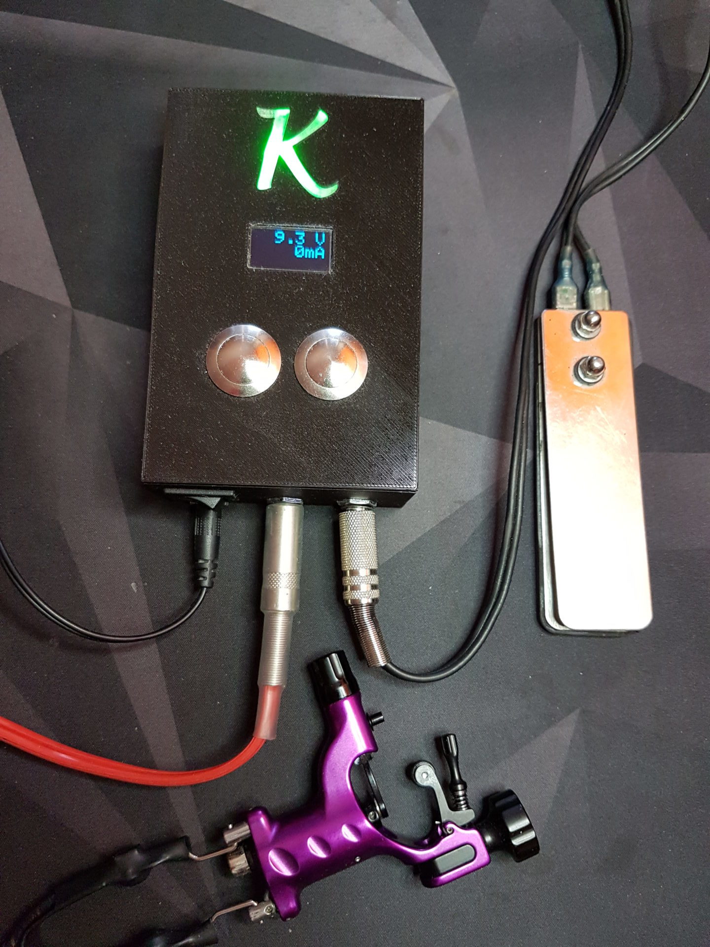
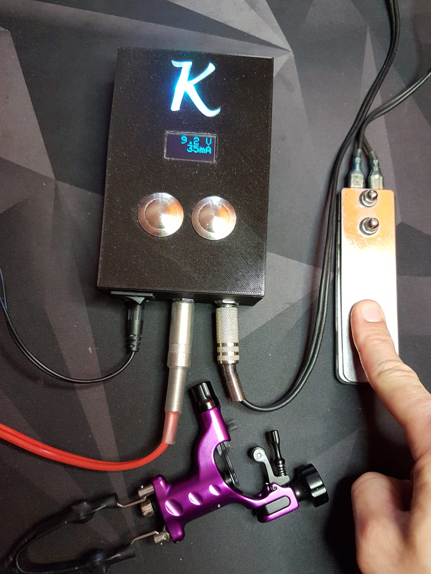
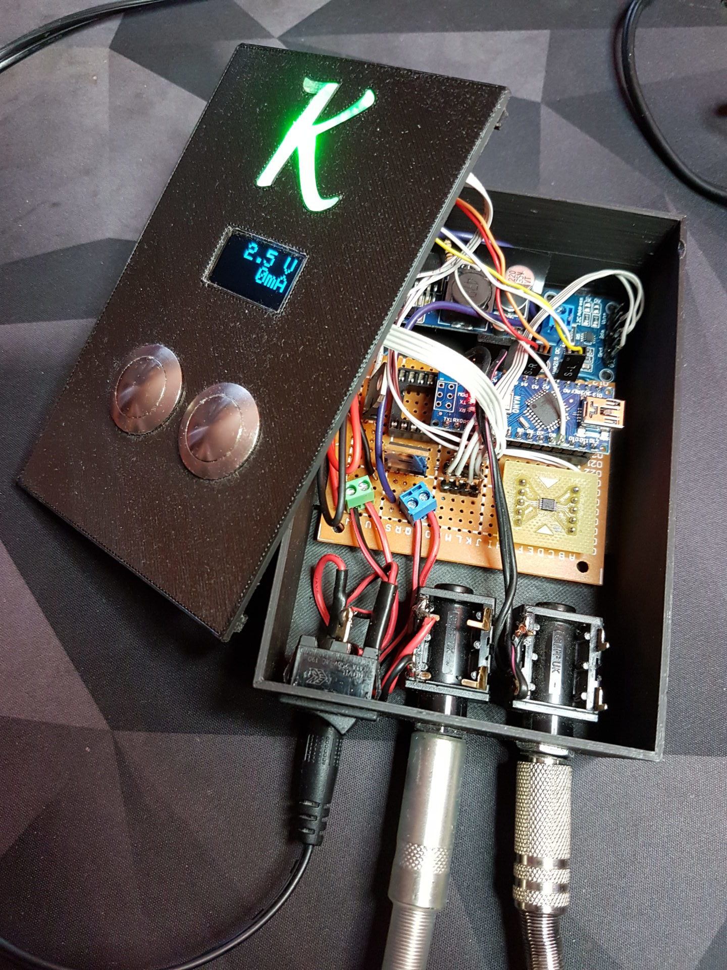
Photos
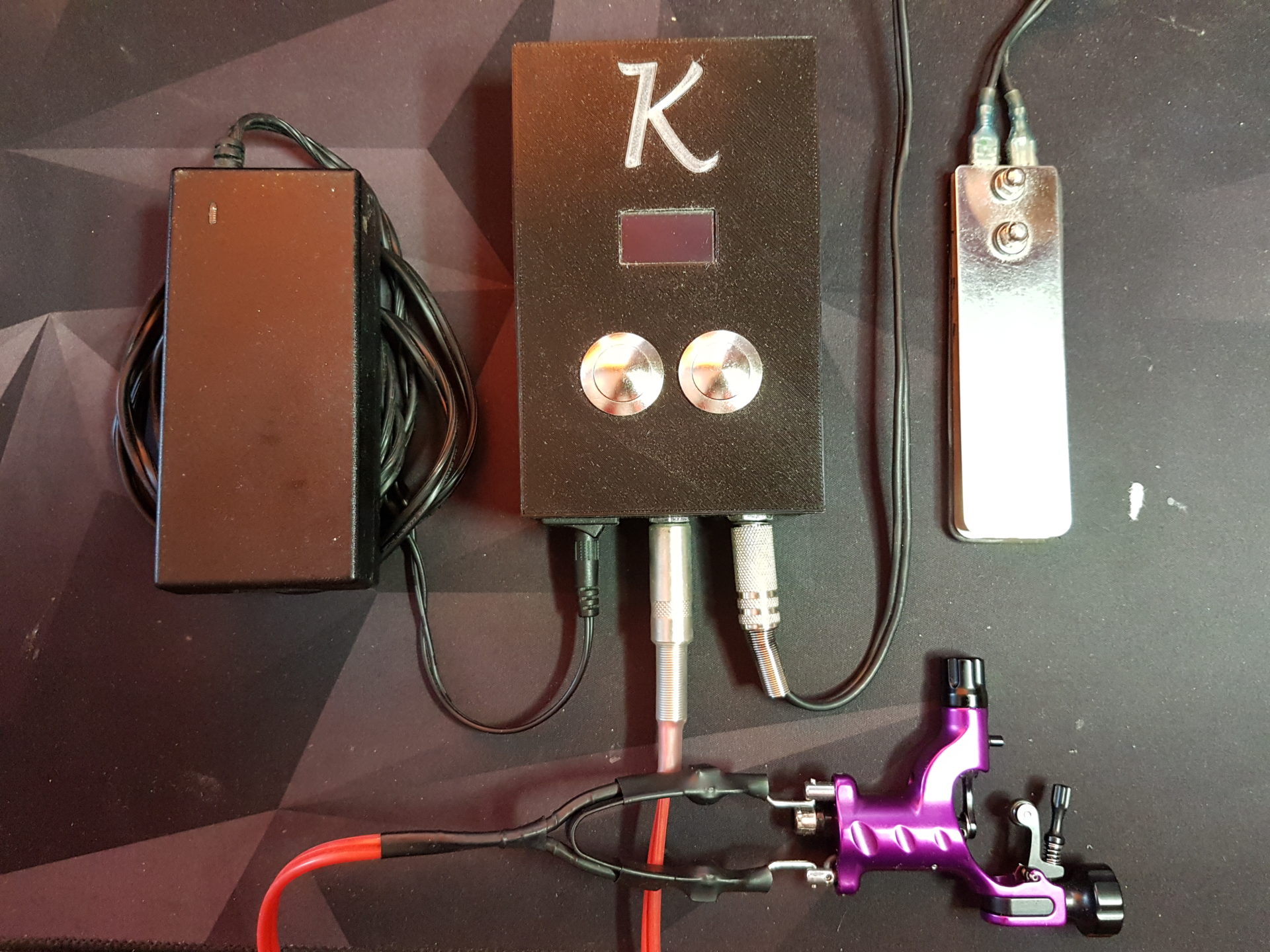
Description
This architecture uses ardunio as control logic. The idea was to enable controlled, step changes to output voltage. This was achieved by using a digital potentiometer AD5290, which is a 30V, 8-bit, SPI controlled IC (I made a mini breakout board for it; the package is MSOP-10) Two monostable buttons are ustilized as user input, while an OLED 128×64 display serves as a readout interface. The momentary voltage and current can be read via INA219 Sensor Module, which shares the I2C bus with the aforementioned display (the reading are filtered – averaged – for convenience). The actual power conversion takes place through a LM2596-based module, that had it’s mechanical potentiometer removed has been hooked up to AD5290 terminals. The actual PSU output is switched by a MOSFET, who’s gate is controlled digitally.
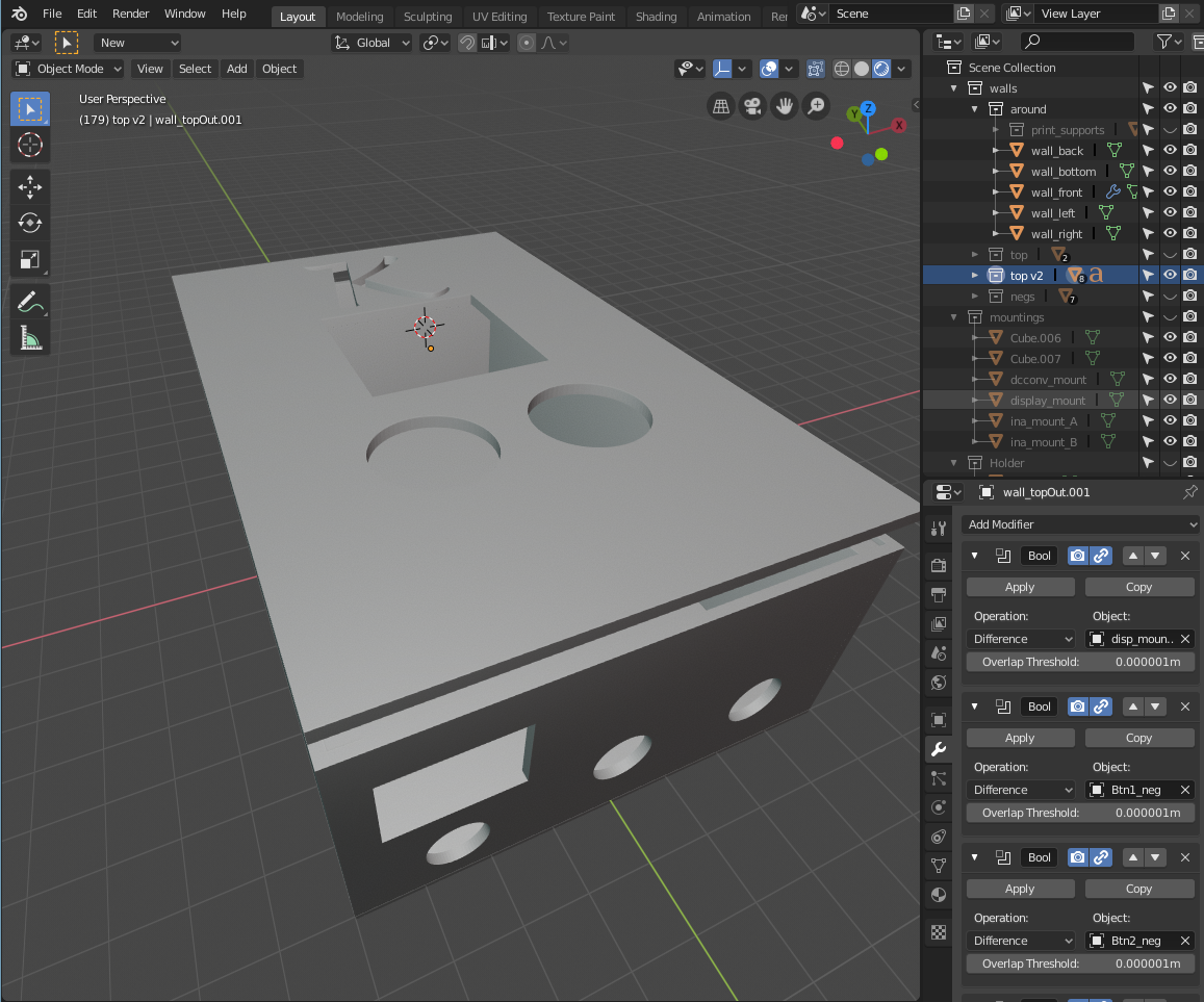
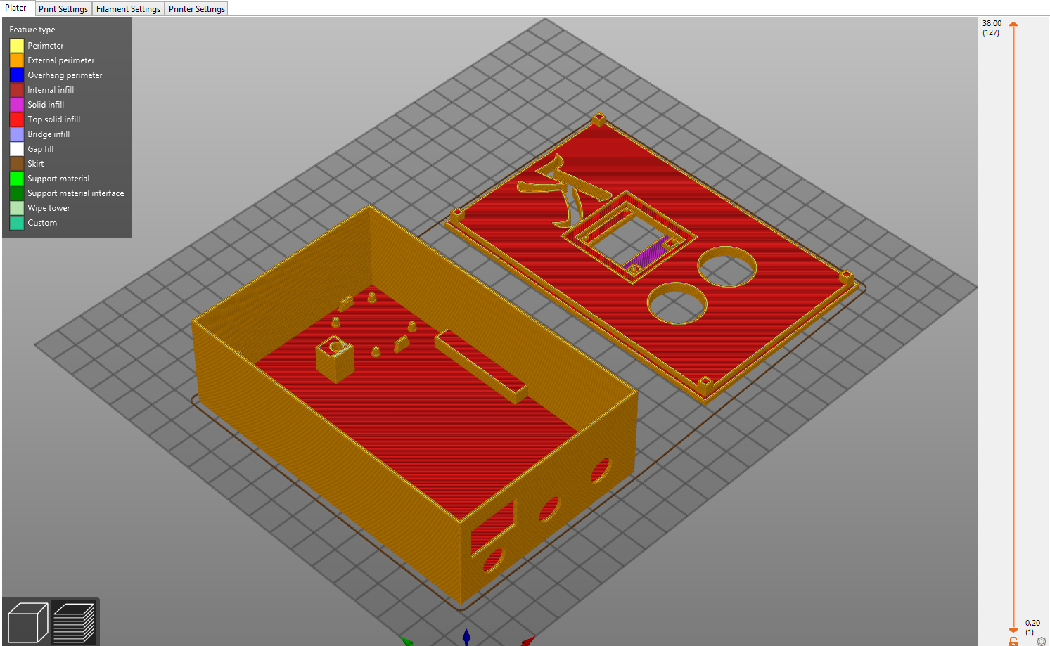
The case was designed with blender (which I realise might not be the best choice for this kind of work). It was printed on Prusa MK3S.
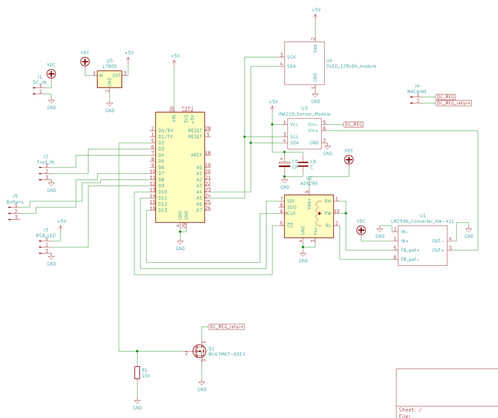
Below you can find schematics for the circuit (the MOSFET’s type name is just a placeholder though)
Below you can find schematics for the circuit (the MOSFET’s type name is just a placeholder though)
Source code
In the archive below you can find a source code for arduino: