

Loud, visible effects, huge coils of wire and dangerous, thrilling discharges – doesn’t this give u shivers? So, as you do, I wanted to build one. There is a lot of physics behind this all and I quite frankly didn’t feel like going through it in detail just yet; that is without allowing myself for a hands-on experience first. There is a ton of examples and approaches on the Internet, so I went through some of them and cherry-picked what I found important.
Now – this area can be quite dangerous, as it may involve substantialy high voltages and poses a risk to health and life. Please DO NOT attempt if you are not sure what u are doing.
Being an electronics engineer I assess my knowledge of electricity to be sufficent for some degree of exploration and I take responsibility for my actions. I’m quite comfortable playing with this idea to certain limits. This project aims to deepen my knowledge of this phenomenon. I’m stepping with reasonable care and attention.
First tries
First thigs first: what is going to be built here is known as a slayer exciter circuit (sometimes also called a “poor man’s tesla coil”, which is fun). The difference is that, in the contrary to real tesla transformer, it uses DC as input.
Lets get some schematics and see what has to be done. Here’s just one from theorycircuit.com:
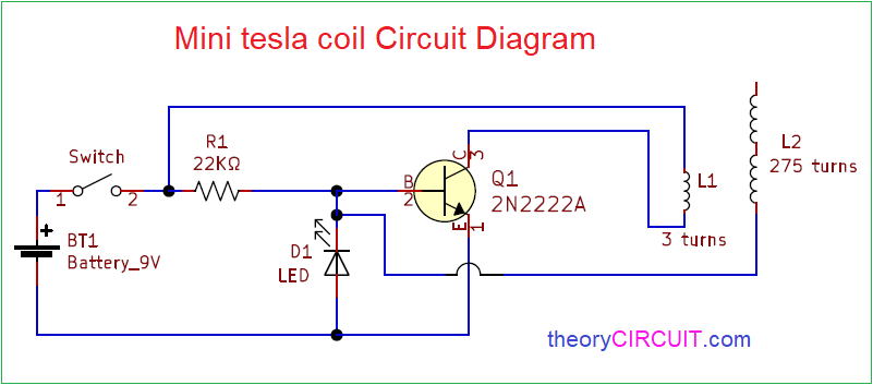
Seems pretty straightforward. I mean things are there: air coupled coils with high winding ratio, primary practically across the supply, secondary obviously connected to give some feedback to the base of a transistor. In theory this thing should self-oscillate, given some conditions are met. For now I dont know those in detail, but I can surely put it all together…
… and there it is losely assembled on a breadboard:
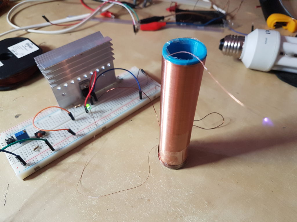
Quite suprisingly it even works (as indicated by the spark). The power was supplied using a bench PSU at around 40V. The secondary has around 500 turns, primary around 4, which puts the theoretical voltage peak at around 40*(500/4)~=5kV (this looks quite serious).
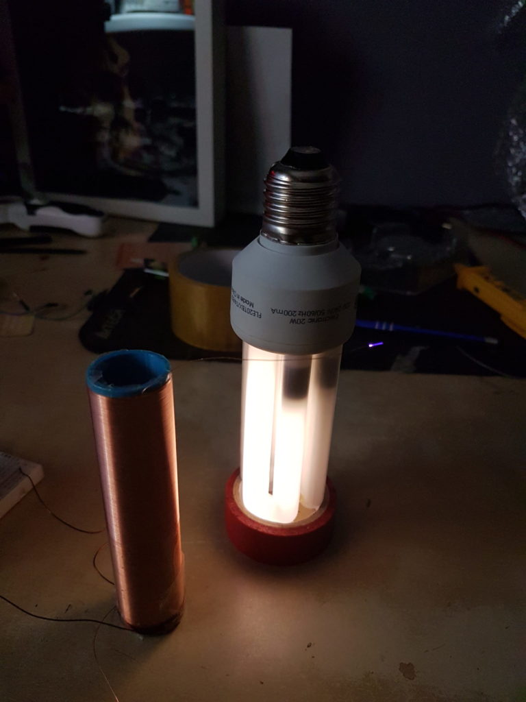
Here you have it powering a fluorescent light bulb:
First upgrade time
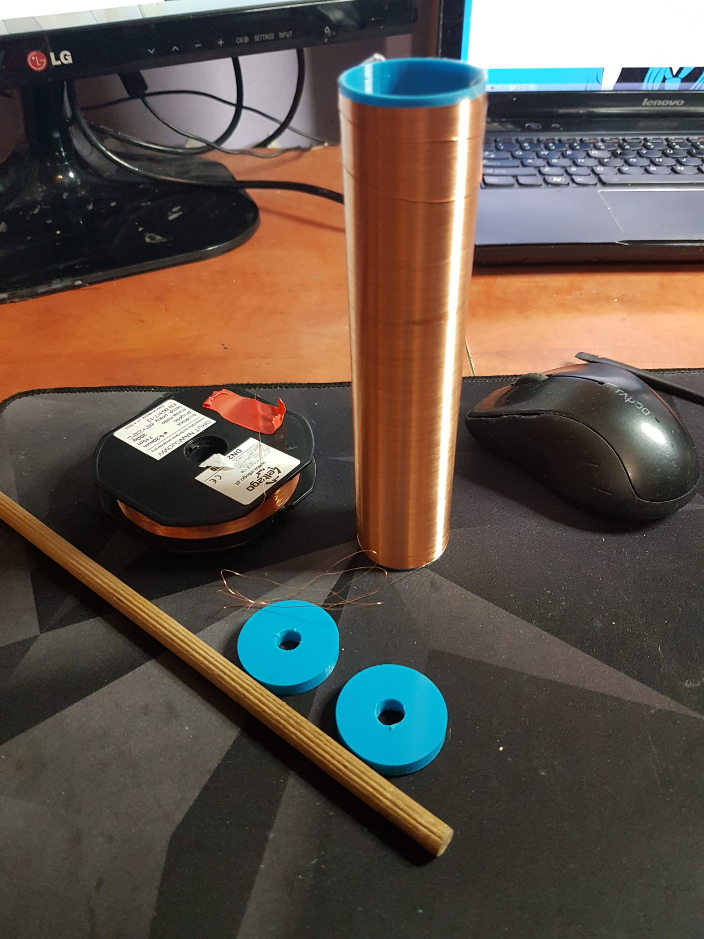
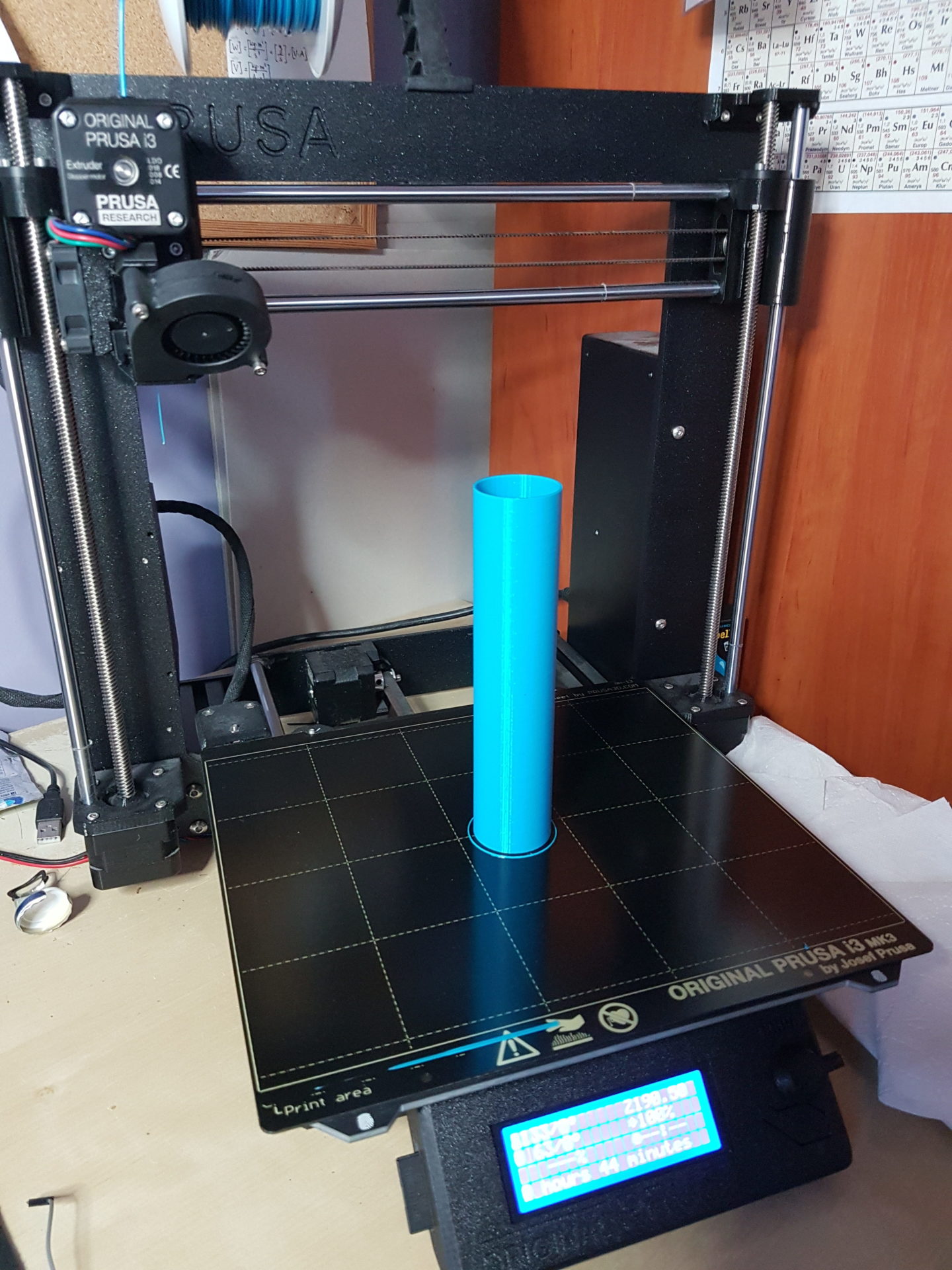
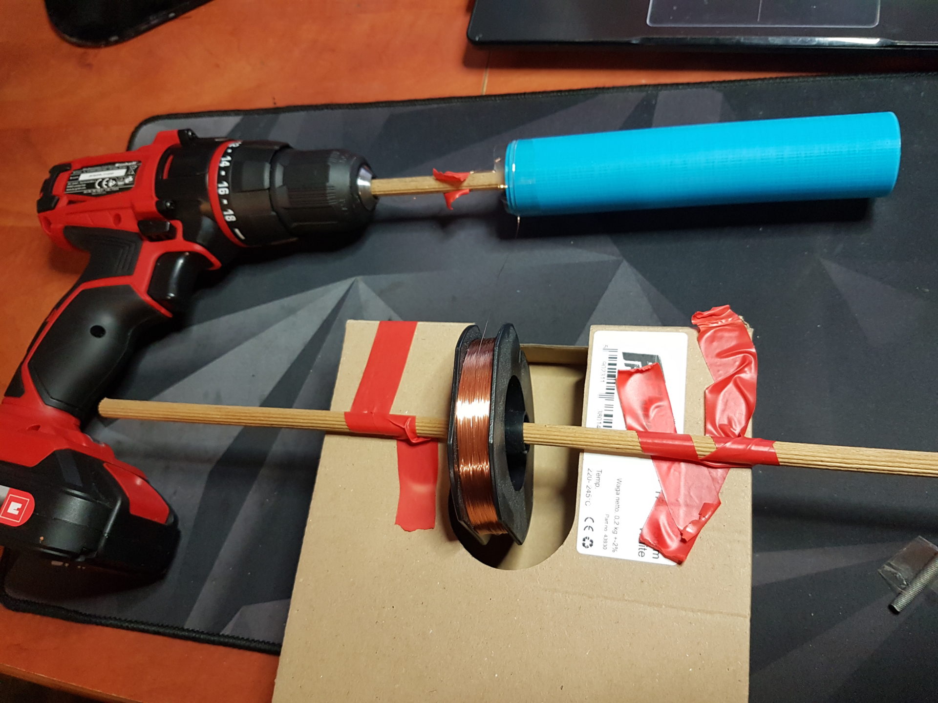
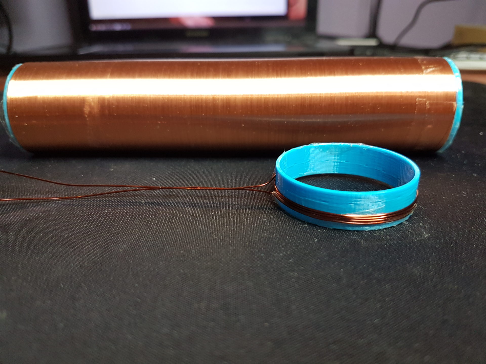
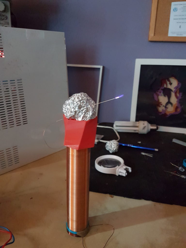
After playing with it for some time I concluded: more power needed (obviously). So i made another secondary. This time a bit wider and higher. There it is:
The cooling system was upgraded to an active one. This is slightly an overkill, but I’d rather see it freeze than melt. The circuit was moved from a breadboard to improve connections. A top load was added, which doesn’t seems to make much difference for now, but this might just be because it’s a totally random ball of tin foil.
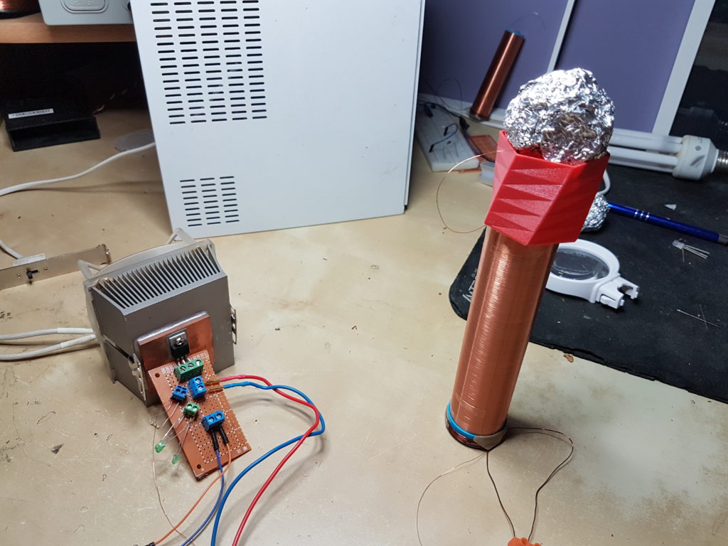
The arc has improved noticeably. It is quite longer and slightly more audible.
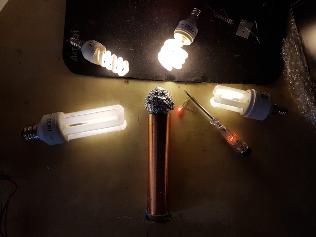
And of course more fluorescent lights:
The funny thing now is that I’m being less and less able to properly film/photograph this thing – it’s field is strong enough to mess up with electronics at quite a distance (around <60cm). Alternatively I can place myself as a ‘coupler’ – holding both hands reached out, one hand near the coil and the other near my monitor’s touch buttons – they’re just getting randomly triggered.
I’m thus attempting to shield the surrounding. For now it’s just pieces and sheets of metal. My phaser777 is behaving as though such a solution is helpful. Placing a metal sheet underneath the coil though visibly diminishes the arc.